1A. Open garage with passive IR detectors
50 Hz or non-dimmable HF operating devices
| Premises
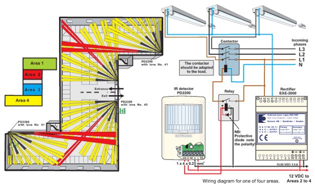
If the garage is on several levels or designed as a multi-storey with openings to the outside, passive IR technology must be used. This also makes it possible to subdivide large garages into different areas to avoid lighting unused areas. This application shows subdivision into four different areas controlled separately. At the entrance vehicles turn left or right and thereby light up the side and area in question. A disadvantage of IR detectors is that high vehicles may conceal the detector. Light sources This application shows an example of fittings with 50 Hz choke operation or non-dimmable HF operating devices. Positioning of detectors In this example the lenses have been replaced by Nos. 41 and 45. The range of these lenses is 41 and 58 m respectively and two long-distance fields of up to 83 m. The opening angle is 90°. This means they must be positioned in corners and in intercepting locations in front of entrances so that passage will be at 90° to the fields of detection. The example provides good insight into how to optimise positioning of the detectors. Unfortunately one all too often sees detectors mounted flat on the wall and aimed at doors and entrances, with the consequence that detection is considerably impaired. |
Control system
Regarding control of the light sources, with 50 Hz operation and non-dimmable HF devices one is referred to control on the power side, i.e. let the detectors control the contactors. This will cause increased wear to operating devices and light sources. To alleviate this, fittings with 50 Hz choke operation should be provided with electronic activators of the type Aura Light ‘Strike’ or similar. Building installations of this type in new productions and renovations is reprehensible. If you have basic lighting whereby certain fittings are switched on constantly, this creates differing maintenance frequencies for different fittings. You miss out on the opportunity of saving up to 20 per cent during operation and running the operating devices at a lower temperature, which can considerably prolong the life of the HF devices. And the operating times for the fluorescent tubes in the installation described here can never be set as short as with Dynamic Control. Please consult the light-source manufacturer.
This application does not show a system that gives the biggest possible energy saving. A garage can be regarded as a frequently used area. Consider using a dimmable ballast with 110 V control and the appropriate control method. Take a look at dynamic lighting control applications!. This is the only method that allows you to create the ideal installation. See the power consumption diagram below! Information for current budget
|
||||||||||||||||
 |
|||||||||||||||||
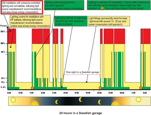
Power consumption diagram The diagram shows a comparison of the power consumption of different systems for presence-controlled lighting in a Swedish garage. The red curve shows the power consumption in a system that is described in this application (1A). It can clearly be seen that the saving could be much higher see the yellow and green curves. This type of presence-controlled lighting is not good and we do not recommend it. |
The yellow curve shows the energy consumption for the same type of control system but with non-dimmable HF ballasts. These light fittings reduce the energy consumption by 25 per cent but produce the same amount of light. The green curve shows the energy consumption for a system with dimmable HF ballasts and “dynamic lighting control”, which gives by far the biggest energy saving. See also the applications in the “Planning guide” that are marked “dynamic lighting control”, and take a close look at application 1F for garages. This application shows a system where the lighting is also daylight-dependent. |
||||||||||||||||
 |
|||||||||||||||||