12B. Photocopier rooms, storerooms, laundry rooms, etc., with sporadic use
IR detector and 50 Hz, non-dimmable or dimmable HF ballast or incandescent light
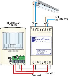
| Premises This solution is suitable for new builds. For installations in existing premises please see application 12A. In this type of area it can sometimes be difficult to justify an investment in lighting control by presence detection on financial grounds alone. The investment cost using existing technology is too high in relation to the saving that can be made. This relatively simple system entails a relatively small investment, which contributes to the shorter payback time, especially if the alternative is that lighting is left on 24 hours a day. Often it can be easier to justify the investment by including other benefits in the costing, such as environmental savings and comfort improvements. Future rises in energy costs, improvements in technology and falling costs of technology can also make it profitable to invest in lighting control by presence detection in this type of room. Light sources Control is achieved by switching off the electrical supply. This means that all types of light fittings can be used, such as light fittings with a 50 Hz coil ballast, HF ballast or incandescent bulbs. Control The system is fully automatic, which means that presence is detected by the IR detector when someone enters, and the lighting is switched on. When no one is present the lighting is switched off after a delay set at the detector. In premises with a source of daylight, the built-in light sensor in the IR detector can be used to prevent lighting from being switched on when there is sufficient daylight. The system is supplied directly with 230 VAC and supplies 230 VAC direct to both resistive and inductive loads up to a maximum rating of 2,300 VA. The control unit that replaces the contactors is mounted on a DIN rack in the electrical distribution panel and is three modules wide. The unit is fused for the connected load, which must not exceed 10 A. Placement of detector Placement of the detector is critical to operation! The diagram illustrates how the detector should be placed. In this refuse room a standard number 15 lens is used. The choice of lens will depend on the layout and use of the premises; see the lens library. The detector is placed so that it cannot see through the doorway, so that the lighting is not switched on when someone passes the door if it has been left open. |
Information for current budget
|